Difference between revisions of "PCB milling"
(Adding more scary warnings to the top) |
|||
| (19 intermediate revisions by one user not shown) | |||
| Line 1: | Line 1: | ||
| + | {{RedTool}} | ||
| + | |||
This page is intended to contain instructions on milling PCBs using the [[Equipment/CNC_Model_Mill|Roland CNC Mill]]. It is still a work in progress. | This page is intended to contain instructions on milling PCBs using the [[Equipment/CNC_Model_Mill|Roland CNC Mill]]. It is still a work in progress. | ||
| − | * The Roland CNC Mill is class red equipment - you MUST NOT use it without specific training. | + | * '''The Roland CNC Mill is class red equipment - you MUST NOT use it without specific training. |
| − | * The Roland's communal milling bits will be easily damaged by copper and fiberglass - do NOT use the communal milling bits! | + | * '''The Roland's communal milling bits will be easily damaged by copper and fiberglass - do NOT use the communal milling bits! Use only dedicated PCB tools. |
| + | * '''Machining PCBs will always damage the bed - do NOT use the main public milling bed for PCBs! | ||
| + | |||
| + | Generally the Roland Model Mill should not be used to machine metal. An exception is made for PCBs provided you are experienced with using the Model Mill, using your own mill bed and using your own PCB cutters. Approved by Paul Osborn on 2nd Sept 2014. | ||
| + | |||
| + | == Introduction == | ||
The toolchain described on this page is as follows: | The toolchain described on this page is as follows: | ||
| Line 15: | Line 22: | ||
== Export from Kicad == | == Export from Kicad == | ||
| − | Download the example Kicad project from | + | Download the example Kicad project from here[http://wiki.makespace.org/images/c/cc/WS2812B_breakout.zip], open "WS2812B_breakout.pro" using Kicad, and then open the PCB editor. You should be faced with a routed board, all ready to be exported. |
| + | |||
[[Image:Initial_Kicad.png|The project on first opening in Kicad.]] | [[Image:Initial_Kicad.png|The project on first opening in Kicad.]] | ||
| + | |||
Click on the button "Offset adjust for drill and place files" in the bottom right (circled in the above image). Click on a point somewhere below and to the left of the components in the above image. This origin MUST be placed at least 2.54 mm below and left of all of the components, traces, board outline, etc (though not those blue dimension labels) otherwise CopperCAM will misalign the layers. | Click on the button "Offset adjust for drill and place files" in the bottom right (circled in the above image). Click on a point somewhere below and to the left of the components in the above image. This origin MUST be placed at least 2.54 mm below and left of all of the components, traces, board outline, etc (though not those blue dimension labels) otherwise CopperCAM will misalign the layers. | ||
| Line 24: | Line 33: | ||
* Make sure the "Back" and "Front" layers are selected. | * Make sure the "Back" and "Front" layers are selected. | ||
Now hit the "Plot button" in the lower right. This image below shows the export options I use - I do not know exactly which of these are crucial. | Now hit the "Plot button" in the lower right. This image below shows the export options I use - I do not know exactly which of these are crucial. | ||
| + | |||
[[Image:Kicad_gerber_for_copperCAM.png|Export options to produce a Gerber that CopperCAM is happy with.]] | [[Image:Kicad_gerber_for_copperCAM.png|Export options to produce a Gerber that CopperCAM is happy with.]] | ||
| + | |||
This should have produced files "WS2812B_breakout-Front.gtl" and "WS2812B_breakout-Back.gbl". Click on the "Generate drill file" button in the bottom right of the "Plot" window. You are now presented with a bewildering array of options. A set that I have found to work are: | This should have produced files "WS2812B_breakout-Front.gtl" and "WS2812B_breakout-Back.gbl". Click on the "Generate drill file" button in the bottom right of the "Plot" window. You are now presented with a bewildering array of options. A set that I have found to work are: | ||
* "Drill Units" to "Inches" | * "Drill Units" to "Inches" | ||
| Line 31: | Line 42: | ||
* "Drill Origin" to "auxiliary axis" | * "Drill Origin" to "auxiliary axis" | ||
The image below shows the exact options I use. | The image below shows the exact options I use. | ||
| − | |||
| − | == Import into CopperCAM and milling | + | [[Image:Kicad_to_coppercam_drill.png|Export options to produce an Excellon drill file that CopperCAM is happy with.]] |
| + | |||
| + | == Import into CopperCAM == | ||
| + | |||
| + | You should have produced some gerber files in the previous section. Alternately, you can get the ones I made from here [http://wiki.makespace.org/images/b/b8/WS2812B_breakout_gerbers.zip] if you just want to verify that the following steps work. | ||
| + | |||
| + | Open CopperCAM. Go to File --> Open --> New circuit and select the "WS2812B_breakout-Front.gtl" file. You'll be given a dialog about with a certain track is a 'card contour'. Click "no", this is just related to routing out the board. Well use a different program for this. Your window should now look like this: | ||
| + | |||
| + | [[Image:CopperCAM_front.png|The front of the board has been imported.]] | ||
| + | |||
| + | Go to File --> Open --> Additional layer and select the "WS2812B_breakout-Back.gbl" file. Again say "no" to the card contour dialog. You window should now look like this, with the pads lining up correctly with one another: | ||
| + | |||
| + | [[Image:CopperCAM_both.png|Both layers of the board have been imported, and the alignment is correct.]] | ||
| + | |||
| + | Now go to File --> Open --> Drills, make sure the filetype is set to "Excellon, Basic co-ordinates", and select the "WS2812B_breakout.drl" file. You'll be presented with a dialog asking you if the setting are correct, and (hopefully!) the drill holes will be the right size and over the pads. | ||
| + | |||
| + | [[Image:CopperCAM_drills.png|Dialog asking is everything is OK with the drill file import.]] | ||
| + | |||
| + | If so, click 'yes' on this dialog, and you should now see something like the following: | ||
| + | |||
| + | [[Image:CopperCAM_all.png|Layers and drills all correctly loaded.]] | ||
| + | |||
| + | At this point you can use File --> Save to save the file in CopperCAM's native format, for easy re-loading if it crashes. | ||
| + | |||
| + | == Setup CopperCAM for milling == | ||
| + | |||
| + | We now need to select appropriate tools for milling. I shall denote some communal tools, shown below. These are a 0.25mm 45 degree engraving bit, a 0.9mm drill bit, and a 0.8mm routing bit. | ||
| + | |||
| + | [[Image:PCB_tools.jpg|From left to right: engraving bit, drill bit, routing bit.]] | ||
| + | |||
| + | First we need to check that these are actually in the tool library. In CopperCAM go to Parameters --> Tool library and check that the engraving bit is there as tool number 7, and the 0.9mm drill is there as tool number 9. | ||
| + | |||
| + | Now go to Parameters --> Selected tools. | ||
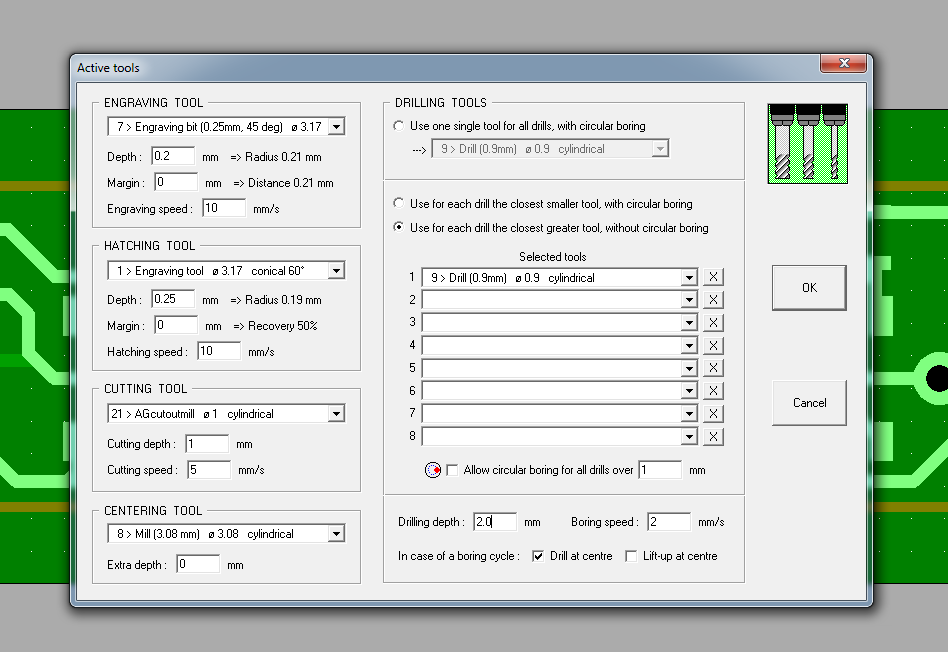
| + | * In the top left "Engraving Tool" section, select tool number 7. Set the "Depth" to 0.2mm, the "Margin" to 0, and the "Engraving speed" to 10mm/s. | ||
| + | * Hatching, Cutting and Centering tools are all irrelevant for this example. And I don't fully understand what they do. | ||
| + | * In "Drilling tools" select "Use for each drills the closest greater tool, without circular boring." Set the first tool in the list to tool number 9, and clear all of the others. Set the drilling depth to 2.0mm. | ||
| + | [[Image:Tool_selections.png|Tool selection settings.]] | ||
| + | |||
| + | Now that you've selected the engraving tool parameters goto Machine --> Calculate contours. This calculates the toolpaths for the engraving jobs that'll be run shortly. | ||
| + | |||
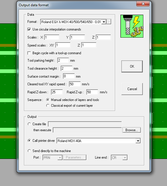
| + | Now go to Parameters --> Output data format. Check that: | ||
| + | * "Format" is set to "Roland EGX & MDX-40/500/540/650 - 0.01" | ||
| + | * "Call printer driver" is selected, and the "Roland MDX-40A" driver is chosen from the drop-down menu. | ||
| + | |||
| + | [[Image:Output.png|Settings to output for the Roland mill.]] | ||
| + | |||
| + | == Set up the machine and mill == | ||
| + | |||
| + | Switch on the Roland mill and maneuver the bed so that it's at the front of the machine. Do NOT mill a PCB on the communal milling bed. The drills will mark the bed when they pass through the bottom of the PCB. I will make a communal PCB milling bed and leave it near the machine. | ||
| + | |||
| + | To remove the communal bed, unscrew the four screws in the corners. Put the PCB milling bed in its place, and screw this firmly in place. Don't over-tighten the screws! | ||
| + | |||
| + | Insert the PCB blank into the pocket in the milling bed, and tighten the nuts to hold it in place. You must be pushing the PCB blank into the BOTTOM LEFT corner, and to the LEFT SIDE while doing this. | ||
| + | |||
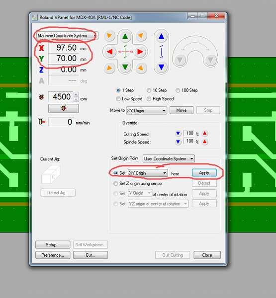
| + | Once the PCB is secured in the bed, switch on the Roland mill and open VPanel. Select 'Machine Coordinate System' from the drop-down menu, move the head to X=97.50, Y=70.00, and click set the XY origin to that point. | ||
| + | |||
| + | [[Image:Machine_origin.png|Setting the origin of the user coordinate system to the bottom left of the PCB.]] | ||
| + | |||
| + | If you have pushed the PCB firmly into the bottom left of the pocket then (0, 0) of the 'User Coordinate System' is now aligned with the bottom left corner of the PCB. | ||
| + | |||
| + | However, we cannot just mill from (0, 0)! The clamps holding the PCB blank will get in the way for a start. Go to CopperCAM, and look in the bottom left hand corner. There are two numbers in the bottom left hand corner showing the X and Y coordinates of your mouse pointer on the CopperCAM screen. (0, 0) in CopperCAM's coordinates will get milled at (0, 0) in the 'User Coordinate System' of the Roland mill. You need to make some judgement here about whether there is enough room at the edge of the circuit to cut it out using a routing bit. In my example there's a few mm gap between the bottom left of the circuit traces and (0, 0). However, in the photos I've put up, you can see I'm using some board that already has holes in it. I want to position my circuit to avoid them! | ||
| + | |||
| + | You achieve this by doing the following: | ||
| + | * Make sure that the 'User Coordinate System' is selected, and the origin of this is set to the bottom left of the PCB (see above). | ||
| + | * Maneuver the tool to the point where you want the bottom left of the circuit to be. | ||
| + | * Write down the (X, Y) coordinates of the (in the User Coordinate System) as (DeltaX, DeltaY). We may need them later. | ||
| + | * Set the XY origin to this point. | ||
| + | * Move the tool to where the top right of the circuit will be, and check visually that it will fit. | ||
| + | |||
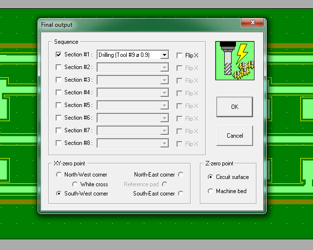
| + | We will do the drilling operation first, since this seems to result in less burring. Insert the drill into the 1/8 inch chuck (imperial chucks for the Roland have a blue end) and insert the chuck into the mill. Set Z0 using the sensor. In CopperCAM go to Machine --> Mill. You should now be presented with a dialogue: | ||
| + | * Make sure the only the 'Section #1' operation is checked, and that it is set to 'Drilling'. | ||
| + | * Make sure that 'Flip X' is NOT checked. | ||
| + | * Make sure the XY-zero point is set to 'South-West corner'. | ||
| + | * Make sure that 'Z-zero point' is set to 'Circuit surface'. | ||
| + | Your dialogue should look as follows: | ||
| + | |||
| + | [[Image:Drill.png|Settings for the drill operation.]] | ||
| + | |||
| + | If you're confident that you've done everything correctly, press 'OK' and the Roland should start to drill the holes. Be ready to hit the E-stop button if it heads towards any of the clamps! | ||
| + | |||
| + | When the spindle has stopped and VPanel has returned control of the machine to you, open the lid and brush/vacuum out the swarf. Change the drill for the engraving bit. Make sure that the chuck is gripping the full shank, not the half-moon section! | ||
| + | |||
| + | Re-set Z0 using the sensor. In CopperCAM go to Machine --> Mill: | ||
| + | * Make sure the only the 'Section #1' operation is checked, and that it is set to 'Engraving layer #1'. | ||
| + | * Make sure that 'Flip X' is NOT checked. | ||
| + | * Make sure the XY-zero point is set to 'South-West corner'. | ||
| + | * Make sure that 'Z-zero point' is set to 'Circuit surface'. | ||
| + | Your dialogue should look as follows: | ||
| + | |||
| + | [[Image:Mill_front.png|Settings for the front milling operation.]] | ||
| + | |||
| + | As with the drilling, if you're confident that you've done everything correctly, press 'OK' and the Roland will start milling. | ||
| + | |||
| + | We now have our holes drilled and our front layer milled, we need to mill the traces on the back. Loosen the clamps, remove the board, flip it left to right, and re-insert it. This time you are trying to push it as far as possible in the BOTTOM RIGHT corner and against the RIGHT side while you tighten the clamps. | ||
| + | |||
| + | In VPanel, select 'Machine Coordinate system' and position the tool at X = 202.50 - DeltaX, Y = 70.00 + DeltaY. Set the XY origin to this point. The 'User Coordinate system' origin is now in the same place relative to the circuit as when the board was the other way up! | ||
| + | |||
| + | Re-set Z0 using the sensor. In CopperCAM go to Machine --> Mill. We need to change the settings a bit for the reverse side: | ||
| + | * Make sure the only the 'Section #1' operation is checked, and that it is set to 'Engraving layer #1'. | ||
| + | * Make sure that 'Flip X' IS checked. | ||
| + | * Make sure the XY-zero point is set to 'South-East corner'. | ||
| + | * Make sure that 'Z-zero point' is set to 'Circuit surface'. | ||
| + | Your dialogue should look as follows: | ||
| + | |||
| + | [[Image:Mill_back.png|Settings for the back milling operation.]] | ||
| + | |||
| + | Congratulations! You should now have a double-sided PCB. All that remains is to cut it out. I find Vectric Cut2D is best for this, since it allows me to leave tabs on the board. | ||
| + | |||
| + | Open Vectric Cut2D. Click on "Create new file." | ||
| + | * Set Z Zero at top, thickness to 1.6mm | ||
| + | * Set the origin in the bottom left. | ||
| + | * Width and height to at least the size of our board (48.8mm x 18.4mm in this example) | ||
| + | |||
| + | Read off the bottom left corner of the board outline in CopperCAM (x = 3mm, y = 3mm in this example). | ||
| + | Set this as the bottom right corner (with x=-3mm) of a rectangle in Cut2D. Read off the width of the outline from CopperCAM (width = 43mm, height = 13mm in this example) and set rectangle accoridngly. | ||
| + | |||
| + | Select this vector and create a profile toolpath | ||
| + | * Cutting depth 1.8mm | ||
| + | * Outside | ||
| + | * Ramp plunges over 2mm | ||
| + | * Add tabs of length 0.5mm, height 0.5mm | ||
| + | * Select the 0.8mm end mill | ||
| − | + | Insert this tool, set Z0. Send the profile to the mill using Cut2D. | |
Latest revision as of 15:06, 2 September 2014
Class Red equipment: Do not use without specific training.
(More about equipment classes)
This page is intended to contain instructions on milling PCBs using the Roland CNC Mill. It is still a work in progress.
- The Roland CNC Mill is class red equipment - you MUST NOT use it without specific training.
- The Roland's communal milling bits will be easily damaged by copper and fiberglass - do NOT use the communal milling bits! Use only dedicated PCB tools.
- Machining PCBs will always damage the bed - do NOT use the main public milling bed for PCBs!
Generally the Roland Model Mill should not be used to machine metal. An exception is made for PCBs provided you are experienced with using the Model Mill, using your own mill bed and using your own PCB cutters. Approved by Paul Osborn on 2nd Sept 2014.
Contents
Introduction
The toolchain described on this page is as follows:
- Design the PCB in Kicad, export to Gerber and Excellon drill files.
- Import the Gerber and Excellon files into CopperCAM.
- Set up appropriate tool choices in CopperCAM, and export these directly the Roland's printer driver.
It should be easy to substitute Kicad for Eagle in the above. I am using Kicad purely because that is what I am familiar with.
CopperCAM is a very temperamental piece of software as regards importing Gerbers and drill files. Most of this page will be devoted to managing its eccentricities. It does, however, seem to output instructions that the Roland mill understands, with some restrictions that will be discussed below.
Export from Kicad
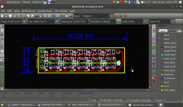
Download the example Kicad project from here[1], open "WS2812B_breakout.pro" using Kicad, and then open the PCB editor. You should be faced with a routed board, all ready to be exported.
Click on the button "Offset adjust for drill and place files" in the bottom right (circled in the above image). Click on a point somewhere below and to the left of the components in the above image. This origin MUST be placed at least 2.54 mm below and left of all of the components, traces, board outline, etc (though not those blue dimension labels) otherwise CopperCAM will misalign the layers.
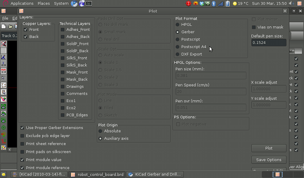
Click on File --> Plot.
- Set "Plot Format" to "Gerber"
- Set "Plot Origin" to "Auxiliary axis"
- Make sure the "Back" and "Front" layers are selected.
Now hit the "Plot button" in the lower right. This image below shows the export options I use - I do not know exactly which of these are crucial.
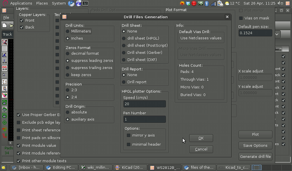
This should have produced files "WS2812B_breakout-Front.gtl" and "WS2812B_breakout-Back.gbl". Click on the "Generate drill file" button in the bottom right of the "Plot" window. You are now presented with a bewildering array of options. A set that I have found to work are:
- "Drill Units" to "Inches"
- "Zeros Format" to "suppress leading zeros"
- "Precision" to "2:4"
- "Drill Origin" to "auxiliary axis"
The image below shows the exact options I use.
Import into CopperCAM
You should have produced some gerber files in the previous section. Alternately, you can get the ones I made from here [2] if you just want to verify that the following steps work.
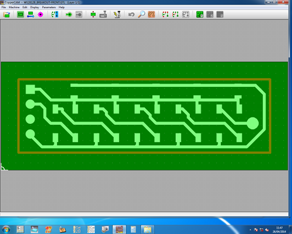
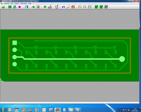
Open CopperCAM. Go to File --> Open --> New circuit and select the "WS2812B_breakout-Front.gtl" file. You'll be given a dialog about with a certain track is a 'card contour'. Click "no", this is just related to routing out the board. Well use a different program for this. Your window should now look like this:
Go to File --> Open --> Additional layer and select the "WS2812B_breakout-Back.gbl" file. Again say "no" to the card contour dialog. You window should now look like this, with the pads lining up correctly with one another:
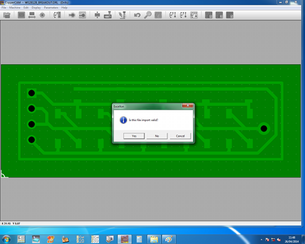
Now go to File --> Open --> Drills, make sure the filetype is set to "Excellon, Basic co-ordinates", and select the "WS2812B_breakout.drl" file. You'll be presented with a dialog asking you if the setting are correct, and (hopefully!) the drill holes will be the right size and over the pads.
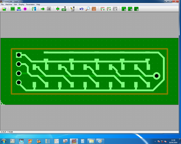
If so, click 'yes' on this dialog, and you should now see something like the following:
At this point you can use File --> Save to save the file in CopperCAM's native format, for easy re-loading if it crashes.
Setup CopperCAM for milling
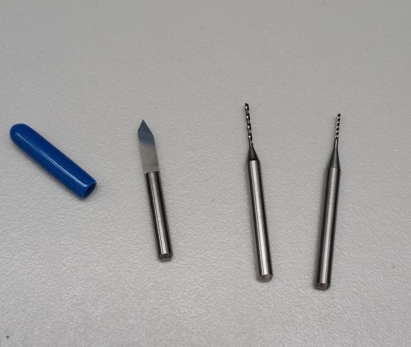
We now need to select appropriate tools for milling. I shall denote some communal tools, shown below. These are a 0.25mm 45 degree engraving bit, a 0.9mm drill bit, and a 0.8mm routing bit.
First we need to check that these are actually in the tool library. In CopperCAM go to Parameters --> Tool library and check that the engraving bit is there as tool number 7, and the 0.9mm drill is there as tool number 9.
Now go to Parameters --> Selected tools.
- In the top left "Engraving Tool" section, select tool number 7. Set the "Depth" to 0.2mm, the "Margin" to 0, and the "Engraving speed" to 10mm/s.
- Hatching, Cutting and Centering tools are all irrelevant for this example. And I don't fully understand what they do.
- In "Drilling tools" select "Use for each drills the closest greater tool, without circular boring." Set the first tool in the list to tool number 9, and clear all of the others. Set the drilling depth to 2.0mm.
Now that you've selected the engraving tool parameters goto Machine --> Calculate contours. This calculates the toolpaths for the engraving jobs that'll be run shortly.
Now go to Parameters --> Output data format. Check that:
- "Format" is set to "Roland EGX & MDX-40/500/540/650 - 0.01"
- "Call printer driver" is selected, and the "Roland MDX-40A" driver is chosen from the drop-down menu.
Set up the machine and mill
Switch on the Roland mill and maneuver the bed so that it's at the front of the machine. Do NOT mill a PCB on the communal milling bed. The drills will mark the bed when they pass through the bottom of the PCB. I will make a communal PCB milling bed and leave it near the machine.
To remove the communal bed, unscrew the four screws in the corners. Put the PCB milling bed in its place, and screw this firmly in place. Don't over-tighten the screws!
Insert the PCB blank into the pocket in the milling bed, and tighten the nuts to hold it in place. You must be pushing the PCB blank into the BOTTOM LEFT corner, and to the LEFT SIDE while doing this.
Once the PCB is secured in the bed, switch on the Roland mill and open VPanel. Select 'Machine Coordinate System' from the drop-down menu, move the head to X=97.50, Y=70.00, and click set the XY origin to that point.
If you have pushed the PCB firmly into the bottom left of the pocket then (0, 0) of the 'User Coordinate System' is now aligned with the bottom left corner of the PCB.
However, we cannot just mill from (0, 0)! The clamps holding the PCB blank will get in the way for a start. Go to CopperCAM, and look in the bottom left hand corner. There are two numbers in the bottom left hand corner showing the X and Y coordinates of your mouse pointer on the CopperCAM screen. (0, 0) in CopperCAM's coordinates will get milled at (0, 0) in the 'User Coordinate System' of the Roland mill. You need to make some judgement here about whether there is enough room at the edge of the circuit to cut it out using a routing bit. In my example there's a few mm gap between the bottom left of the circuit traces and (0, 0). However, in the photos I've put up, you can see I'm using some board that already has holes in it. I want to position my circuit to avoid them!
You achieve this by doing the following:
- Make sure that the 'User Coordinate System' is selected, and the origin of this is set to the bottom left of the PCB (see above).
- Maneuver the tool to the point where you want the bottom left of the circuit to be.
- Write down the (X, Y) coordinates of the (in the User Coordinate System) as (DeltaX, DeltaY). We may need them later.
- Set the XY origin to this point.
- Move the tool to where the top right of the circuit will be, and check visually that it will fit.
We will do the drilling operation first, since this seems to result in less burring. Insert the drill into the 1/8 inch chuck (imperial chucks for the Roland have a blue end) and insert the chuck into the mill. Set Z0 using the sensor. In CopperCAM go to Machine --> Mill. You should now be presented with a dialogue:
- Make sure the only the 'Section #1' operation is checked, and that it is set to 'Drilling'.
- Make sure that 'Flip X' is NOT checked.
- Make sure the XY-zero point is set to 'South-West corner'.
- Make sure that 'Z-zero point' is set to 'Circuit surface'.
Your dialogue should look as follows:
If you're confident that you've done everything correctly, press 'OK' and the Roland should start to drill the holes. Be ready to hit the E-stop button if it heads towards any of the clamps!
When the spindle has stopped and VPanel has returned control of the machine to you, open the lid and brush/vacuum out the swarf. Change the drill for the engraving bit. Make sure that the chuck is gripping the full shank, not the half-moon section!
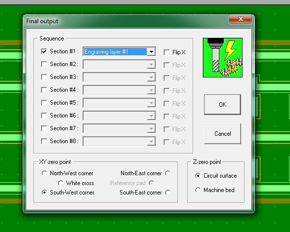
Re-set Z0 using the sensor. In CopperCAM go to Machine --> Mill:
- Make sure the only the 'Section #1' operation is checked, and that it is set to 'Engraving layer #1'.
- Make sure that 'Flip X' is NOT checked.
- Make sure the XY-zero point is set to 'South-West corner'.
- Make sure that 'Z-zero point' is set to 'Circuit surface'.
Your dialogue should look as follows:
As with the drilling, if you're confident that you've done everything correctly, press 'OK' and the Roland will start milling.
We now have our holes drilled and our front layer milled, we need to mill the traces on the back. Loosen the clamps, remove the board, flip it left to right, and re-insert it. This time you are trying to push it as far as possible in the BOTTOM RIGHT corner and against the RIGHT side while you tighten the clamps.
In VPanel, select 'Machine Coordinate system' and position the tool at X = 202.50 - DeltaX, Y = 70.00 + DeltaY. Set the XY origin to this point. The 'User Coordinate system' origin is now in the same place relative to the circuit as when the board was the other way up!
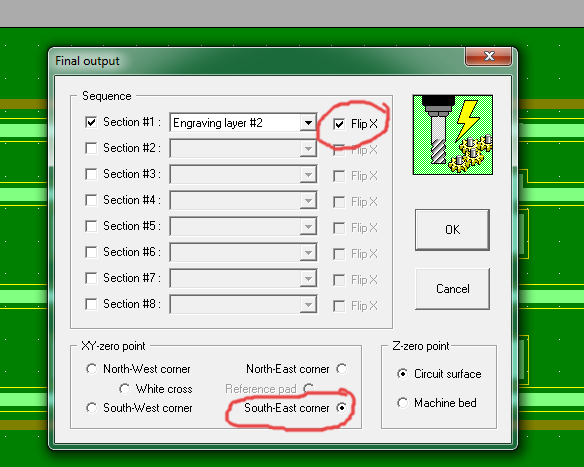
Re-set Z0 using the sensor. In CopperCAM go to Machine --> Mill. We need to change the settings a bit for the reverse side:
- Make sure the only the 'Section #1' operation is checked, and that it is set to 'Engraving layer #1'.
- Make sure that 'Flip X' IS checked.
- Make sure the XY-zero point is set to 'South-East corner'.
- Make sure that 'Z-zero point' is set to 'Circuit surface'.
Your dialogue should look as follows:
Congratulations! You should now have a double-sided PCB. All that remains is to cut it out. I find Vectric Cut2D is best for this, since it allows me to leave tabs on the board.
Open Vectric Cut2D. Click on "Create new file."
- Set Z Zero at top, thickness to 1.6mm
- Set the origin in the bottom left.
- Width and height to at least the size of our board (48.8mm x 18.4mm in this example)
Read off the bottom left corner of the board outline in CopperCAM (x = 3mm, y = 3mm in this example). Set this as the bottom right corner (with x=-3mm) of a rectangle in Cut2D. Read off the width of the outline from CopperCAM (width = 43mm, height = 13mm in this example) and set rectangle accoridngly.
Select this vector and create a profile toolpath
- Cutting depth 1.8mm
- Outside
- Ramp plunges over 2mm
- Add tabs of length 0.5mm, height 0.5mm
- Select the 0.8mm end mill
Insert this tool, set Z0. Send the profile to the mill using Cut2D.
