Equipment/3D Printer/Up
Contents
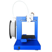
The Up! 3D Printer
YOU CAN ONLY USE THE UP 3D PRINTER IF YOU HAVE BEEN TRAINED ON IT
Being trained on the Makerbot is a different induction from being trained on the Up!
The UP! 3D printer suffered an electronics failure, and has had its control circuitry replaced with a RepRap Melzi controller board. Software required to control the Up! is installed on the 3D printer PC, alongside the Makerbot.
Owners/Trainers: Brian Starkey
Caveats
The Up! is intended for use by those who wish to take more control of the 3D printing process and are interested in experimentation. The software workflow is less-friendly than the Makerbot, but infinitely more flexible.
Operating Instructions
Power-on
The Up! requires two power supplies - a 20V high power supply which drives the bulk of the printer (motors, heaters) and a separate 5V supply which drives the filament feeder.
Both supplies are plugged in to a switchable power strip plugged in to the wall behind the PC - it is marked "Up". Turning this strip on will power up the printer.
Power-down
Before powering off, remember to unload the filament and return it to the box.
Before turning the power off, home all the axes using the White home button or the G-code G28, then turn off the main switch.
Control Software (Pronterface)
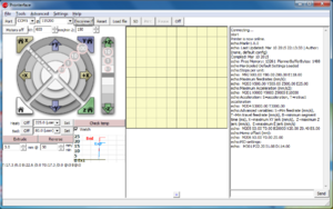
The default control software for the Up! is Printrun, a.k.a. Pronterface, a Python-based Reprap host software.
Printrun 2014.03.10 is installed on the 3D printer PC under Users/makespace-user2/My Documents/Up/Pronterface. There is a shortcut on the Desktop.
Pronterface is only a control software, it interfaces with the printer, however it depends on external software (a Slicer) to turn 3D models into commands that the printer can understand.
Printer startup
After powering on the printer, open Pronterface.
Select the COM port and baud rate in the top-left hand corner. The COM port is normally COM5 and the baud rate is 115200, then click Connect.
After several seconds the command pane on the right of the window should state that the printer is connected and print some details about the machine.
Controlling the printer
G28)Movement
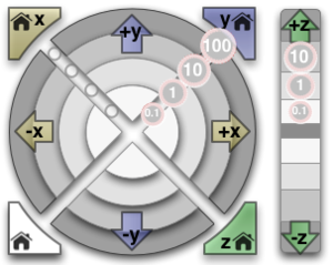
The circular arrangement of buttons can be used to directly control the printer axes. The axis orientation is shown on the picture to the left. e.g. Movement in +Z direction moves the bed further from the extruder
Heaters
The bed and extruder heaters can be manually controlled from the controls immediately below the movement buttons. The temperatures can be monitored by checking the Watch checkbox on the right, which will update the plot in real-time. Clicking the plot will open a new window displaying the temperature plot.
G-code
G-code can be entered in the box in the bottom-right of the window. These will be sent to the printer immediately on pressing "Enter" or clicking the Send button.
The full list of G-code understood by the printer can be found on the RepRap website, supplemented by a few non-standard extensions implemented by the Marlin firmware.
Printing
Loading filament
To load/unload filament, you will need a hot extruder. Use the heater controls to heat up the extruder to the appropriate temperature for the plastic you are loading/unloading.
Once the extruder has warmed up, feed the end of the filament into the underside of the filament feeder and press the microswitch. Press the microswitch a couple more times until sufficient filament is available to feed into the extruder.
In Pronterface, set the extrusion settings to 5mm @ 60mm/min, and feed the filament into the top of the extruder. While gently pushing the filament downwards, click the Extrude button one-or-more times until you can feel the filament being pulled by the extruder. Once the extruder has a hold on the filament, continue to use the Extrude button to feed more plastic, until you get a clean, uniform thread out of the hot-end.
It is often necessary to clear away a blob of plastic from the hot-end during this process.
Filament feeder
The Up! has a small motor which pre-feeds filament from the reel so that the extruder doesn't have to work so hard. The feeder requires power (see [[#Power-on|]]), and will feed for several seconds every time the microswitch is depressed. During printing, the extruder should be able to activate the microswitch itself as it pulls the filament tighter, however it is advisable to keep an eye on it and be ready to press the switch yourself if you think it necessary.
The main risk is that a taught filament causes skipped steps in the X-axis during a rapid move.
Unloading filament
Unloading filament is the opposite of loading. Use the Reverse button in the extruder controls to feed the filament out of the extruder, while gently pulling the filament upwards. You will likely need to click Reverse several times, unless you have set a particularly long extrude length.
The filament feeder is (currently) strictly one-way. Do not attempt to pull the filament back through the feeder!. Use a pair of side-cutters to cut the filament as close to the underside of the feeder as possible, and press the switch to feed it out.
Printing a file
Once you have a G-code file of your sliced model, you can print it from Pronterface.
- Click the Load File button and select your
.gcodefile - Your part should now show up in the middle pane of Pronterface
- Check the output in the command pane on the right looks sensible (i.e. no insane dimensions)
- Click the middle pane to open the G-code viewer, and use the slider on the right to check the slicer output
- The G-code viewer shows movement lines as well as extrusion lines, the movement lines are shown in a different colour
- When you are satisfied, click print in the main Pronterface window!
Pronterface will give an estimated print time when you load the file. In the status bar at the bottom of the window it will continually re-estimate the time remaining throughout the job
Cost
Currently we charge 10 pence per gram for prints, this is to cover the cost of material plus a little for wear and tear and other consumables. You can weigh printed parts using the scales next to the blue honesty box. Please put your money into the blue labelled honesty box on the shelf above the printer.
Bed Levelling/Calibration
The Up! seems to be less sensitive to slight misalignments in the bed than the Makerbot. In part this is probably due to the high-adhesion ABS build plate.
If you do feel the need to level the build plate, then there are 3 allen-key bolts on the underside of the pinkish bed mounting block. The bed rides on 3 silicone grommets, and by adjusting the bolts you can compress the grommets to varying degrees to achieve a level build plate.
At present the bed levelling procedure is a fairly manual affair, requiring entry of G-code into the Pronterface command window. The suggested calibration procedure is given below.
- Load your G-code file into Pronterface.
- Take note of the part dimensions reported in the command window.
- Enter the G-code commands below
- In the G-codes below, the following substitutions should be used:
- <centre_x>, <centre_y>: The build centre coordinates as specified when Slicing
- <min_x>, <min_y>, <max_x>, <max_y>: The minimum x,y coords as shown by pronterface. e.g.: from <min_x> mm to <max_x> mm in X
G28 # Home all axes

# Note: Use Z2 initially to make sure there is enough clearance on the extruder
G0 X<centre_x> Y<centre_y> Z2
# If you are happy that there is 2 mm more space in the Z-axis, continue with the calibration with <z_min> = 0
# Otherwise try larger values of <z_min> (decimals are allowed) e.g. <z_min> = 0.2. Units are in mm
# In this case you should re-slice your part, specifying <z_min> in the Z offset field on the Printer Settings tab

# Repeat the following commands, adjusting the bolts to provide a < 1 mm gap between the extruder and the bed in all positions
G0 X<centre_x> Y<centre_y> Z<min_z>
G0 X<min_x> Y<min_y> Z<min_z>
G0 X<max_x> Y<max_y> Z<min_z>
G0 X<min_x> Y<max_y> Z<min_z>
G0 X<max_x> Y<min_y> Z<min_z>

G28 # Home all axes


