Equipment/CNC Router
Class Red equipment: Do not use without specific training.
(More about equipment classes)
Contents
WARNING
Equipment / CNC Router
Summary
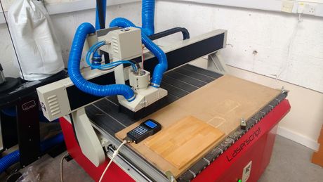
A CNC router is a computer controlled shaping machine. These are related to the hand held router. Instead of hand held routing, the tool paths can be controlled via computer numerical control. It is a computer-controlled machine for cutting various hard materials, such as wood, composites, aluminum, steel, plastics, and foams. It is one of many kinds of tools that have CNC variants. A CNC router is very similar in concept to a CNC milling machine. The CNC router is controlled by a computer. Coordinates are uploaded into the machine controller from a separate CAD program
- Capacity: 1200 x 1200 x 120mm
- Rate (X,Y): 6000mm/min (Max) 5000mm/min (Working)
- Rate (Z): 30mm/sec
- Spindle Speed: 4500 to 24000rpm
- Mechanical Precision: 0.01mm
- Spindle Power: 1.5KW Variable Speed, Water-cooled
- Blade Diameter: min 3.175mm, max 12.7mm
- Order Format: HPGL, G code, u00, mmg, plt
- Control System: DSP with USB connection
Here are some examples we've made on the CNC router (please add a photo of yours any time you do a job!)
Using the CNC Router
Owners & Trainers
The Owners are those who have volunteered to be in charge of the equipment, organising maintenance, training others to use it, and generally being a point of contact. The current Owners of the CNC Router are:
- Mark Mellors
You can email the owners at cncrouter@makespace.org.
Current Trainers:
- Mark Mellors
- Mik Lamming
If you have any questions, problems or concerns around the CNC router, please use the mailing list thread:
Training
YOU CAN ONLY USE THE CNC ROUTER IF YOU HAVE BEEN TRAINED
and have been added to the Trained Users list by one of the Owners or Trainers
To get trained on the CNC router and be added to the qualified user list, you will need to arrange for a training session with one of the Owners or Trainers.
If you'd like to arrange training, please see:
Health and Safety
The CNC Router is a potentially dangerous piece of equipment which must only be operated by members who have received appropriate training and who take due care. The top things to always remember when using the CNC Router are:
- ONLY USE THE CNC ROUTER IF YOU ARE ON THE LIST OF TRAINED USERS
- NEVER LEAVE THE CNC ROUTER RUNNING UNATTENDED
As a trained user, you should be very aware of the following risks and how to deal with them:
FIRE - Cutting with the wrong settings could result in the material igniting.
TRAPPING - Stand clear of the machine while in motion.
DUST - Ensure extraction system is working.
NOISE - Ensure that you wear the correct PPE when working with the machine for prolonged periods.
Full Risk assessmentFile:CNC Router.pdf
Material
It is safe to use wood, plastics and foam with this machine. The way the CNC Router is set up in Makespace means metal is not allowed on the machine: there is no coolant feed or extraction suitable for metal work. For anything else please contact the owners before use if unsure.
CNC Glossary
As with most new ventures into another profession or hobby, there is the need to learn a “new language” and its common abbreviations. We have introduced some of these in the description of the workflow process above. Here we’ll look at some in more detail. These are listed in alphabetical order.
2D/2.5D/3D Toolpaths
Depending on the information source, the definitions of 2D, 2.5D and 3D can be quite vague and appear to overlap.
2D is simple horizontal cuts at a constant Z depth. For example, you cut out letter or a plaque shape to hang on the wall by moving the tool down to a specific depth and tracing the shape of the part you are cutting in 2D.
2.5D would be a little more complex than 2D as while the tool is cutting, the Z depth would be changing instead of staying constant. Typically this still uses 2D vector data to define the path but the way the tool moves in relation to the 2D data and its form will determine the shape that is cut. The most common example of 2.5D is VCarving. Although this cuts 2D vector shapes, the V-shaped tool “rides” on the edges of the vectors, so as it gets wider it cuts deeper and as the vector get closer together it will lift up in Z.
3D' These are toolpaths that like 2.5D toolpaths can move simultaneously in all 3 (X, Y and Z) axes however the shape they cut is described by following a 3D computer model and not vectors. They are typically cut with a Ball-Nose (round ended) tool. The tool will go back and forth across the 3D model following the contours of the part similar to an old fashioned copying or digitizing machine. The smoothness of the finished part depends on the Stepover setting in the toolpath as that determines how many times the tool will pass over the model. The size of the tool is also important as the software will only let it cut the detail that the end of the tool can fit into as it traces over the virtual surface. Examples of 3D toolpaths are 3D Rouging and 3D Finishing
3-axis
A 3-axis CNC machine is one that can move a router bit in the 3 primary directions, X, Y and Z. The image below show 3 views of a typical CNC setup and how the axes are referenced from each viewing direction.
CAD
CAD has been used as an abbreviation for both “Computer Aided Design” and “Computer Aided Drafting”. Now it has become a generic term in its own right that refers to a software program that can be used to create a 2D or 3D design.
CAM
When you discuss designing and preparing projects for your CNC machine, the follow-on side of CAD is CAM, which stands for ‘Computer Aided Manufacturing’ or ‘Computer Aided Machining’. This is the part of the process where the geometry developed during the CAD design process are now used to create the instructions that will move your CNC machine to ‘manufacture’ or machine the part.
Collet
The collet assembly is the component on a router or spindle that holds the router bit securely and consists of a precision collet and a collet nut. The collet is precisely sized to hold the router bit shank and the collet nut applies a compressive, friction fit as it is properly tightened onto the router or spindle shaft. It is very important to keep the collets clean and well maintained and depending on use, they must be periodically replaced.
Gantry
The gantry is the part of a CNC machine that typically has one of the horizontal axes running along it and also moves along the other horizontal axis to create the X and Y movement for the tool. The Z axis is also typically mounted on the gantry.
G-Code
This is a generic term for the code which is sent to the machine with the instructions telling it how to move. Or, to put it in our context, the file that is saved from the software using the Post Processor to format it for the CNC machine. In reality it’s a particular type of data that a lot of CNC’s use a variant of – so G-code is not necessarily interchangeable to different machines. The name comes from the fact that many of the codes within in start with a G. For example G01 specifies a Feed Rate move and G00 specifies a Rapid move etc.
Pass
When you have a toolpath that is too deep, too wide or a combination of both for the router bit to remove all the material at one time, the toolpath is broken up into multiple ‘Passes’ with each pass removing a part of the material.
When the toolpath is too deep, a Pass Depth (see entry below) value for the bit will be set and used to indicate the maximum Z depth the tool should cut on each Pass. The amount of material a tool can remove will be determined by the tooltype, size, material being cut and many other parameters. Tooling manufacturers typically offer recommendations for these values.
Post Processor
There are hundreds of different brands and models of CNC machines currently in use. When it comes to controlling them, many have a lot in common, but there can and will be differences. So, if you look at this as each machine speaks a slightly different language, there has to be a way for a single CAD/CAM program to speak to each machine and this is accomplished by using an “interpreter” called a Post Processor, also sometimes simply referred to as ‘pp’ or ‘post’.
For example, you design a project to cut an exact size circle out of a piece of material and calculate a toolpath to do that. When you actually save that toolpath so it can be used at your CNC machine, the correct Post Processor will ensure the instructions for cutting that circle are prepared correctly so your CNC machine can read and understand them and accurately cut the circle as you intended.
Router Bed or Machine Bed
The ‘bed’ identifies the part of a CNC machine where the material being machined is placed and held securely in position. For best results, the bed needs to be flat and sturdy. In most designs the bed is stationary; however there are exceptions to this where the bed moves to provide either the X or Y axis movement.
Sacrifice Sheet / Spoilboard
The spoilboard is normally a sacrificial sheet of material placed on top of the machine bed and is intended to be replaced as necessary. It protects the machine bed and allows frequent surfacing which will help to keep a truly flat surface to mount material and help maintain accuracy. This allows the stock material to be screwed down to it and the parts drilled and cut all the way through the material thickness.
Stepover
The Stepover setting found for most router bits allows you to control horizontal movement when machining areas wider than the router bit. Physically, stepover is the distance the center of the bit moves horizontally for each pass.
The Stepover is shown in the programs as both a physical distance (0.025” or 0.5mm for example) and as a percentage of bit diameter (6%, 8%, 50%, etc.). You can enter either value and the software will automatically calculate the other one for you. Typically most users refer to Stepover by its percentage value as it is a simple whole number and can easily be translated to other tool sizes for a particular task, for example when finishing setting the Stepover to be 10% of the ballnose tools diameter normally creates a reasonably finish surface.
Toolpath
A toolpath is the path created during the CAM part of your project design and represents the instructions your CNC machine will use to make the router bit move to duplicate what you have designed. In the software it is typically displayed as a set of lines which show a virtual picture of the path the tool tip will move along when the toolpath is run on the machine.
Vector
Vector is the word used to describe a 2D line, arc or curve. A vector can be used to describe almost any 2D shape.
Instructions
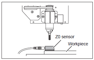
Setting the Z Origin Using the Z0 Sensor
A tool that has an extremely narrow tip may break when it touches the tool sensor depending on which tool is to be used.
1. Secure the workpiece on the bed, and place the Z0 sensor at the place where you want to set the Z origin on the workpiece. Face the surface of the Z0 sensor without the magnet facing upward.
2. Use the handset to move the tool to the position above the sensor.
3. On the handset press OK + 8(Z-0). The tool slowly descend until it contacts the sensor. When the tool rises and stops, the setting operation is complete.
Note: It is important the tool is electrically conductive from tip to shaft, and the sensor is clean. Failure to check will cause damage to the tool and sensor.
4. Remove the sensor from the workpiece to a location where it will not interfere with future cutting operations.
Software
The standard software is Vectric's line of CAM software:
VCarvePro
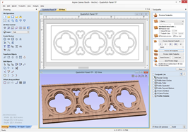
VCarve Pro provides a powerful but intuitive software solution for 2D design and calculation of 2D and 2.5D toolpaths for cutting parts on a CNC Router.
The software can import 2D designs from other programs but also includes a full set of drawing and editing tools with advanced layout options such as True-Shape Nesting. The toolpath options cover all typical 2D routing operations such as Profiling, Pocketing, Auto-Inlays and Drilling as well as 2.5D strategies such as V-Carving, Prism carving, Fluting and even a decorative Texturing strategy. Each toolpath includes appropriate options to customize the settings and provide a high level of control for different types of operation. In addition all toolpaths can be previewed to show just how the part will look when it is actually cut, this allows instant feedback to allow toolpaths to be further optimized.
Details: http://www.vectric.com/products/vcarve-pro.htm
Training Resources: http://support.vectric.com/training-material/vcarve-pro
Cut3D
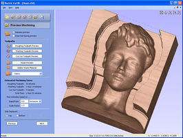
Cut3D is a dedicated toolpath engine for CNC machining 3D models that have been designed using a 3D CAD or Graphics design product such as AutoCAD, Rhino3D, 3D Studio etc. or scanned using a laser or touch probe device. Cut3D's exceptionally easy to use interface leads you step-by-step through the process of loading a model, setting the size, interactively placing tabs to hold the job in place, calculating single, double or four sided roughing and finishing toolpaths, previewing the results and finally saving the CNC code to run on your machine.
3D Models that are too large / thick to machine because of gantry height, cutter length or limited material thickness can be 'Sliced' into separate pieces. Each slice can then be machined and the complete job assembled.
Details: http://www.vectric.com/products/cut3d.html
Training Resources: http://support.vectric.com/training-material/cut3d
PhotoVCarve
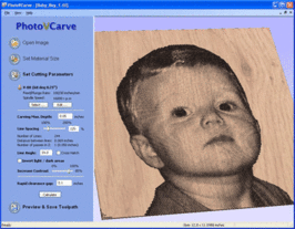
PhotoVCarve creates lines of grooves that vary in width and depth to represent the detail in a photograph or image. The quality of the finished result is very dependant upon a high level of contrast between the material surface and the machined grooves. This information is very important to remember when cutting designs using the PhotoVCarve software.
PhotoVCarve machines dark areas in a photograph with wide groove and the lighter areas to have narrower ones. The software automatically calculates the toolpaths based on the cutter selected and maximum depth of groove required.
Details: http://www.vectric.com/products/photovcarve.html
Training Resources: http://support.vectric.com/training-material/photovcarve
Post Processor for this machine
The CNC router controller expects G Code instructions. In the Vectric line of software select 'G-Code Arcs (mm) (*.tap)' as output post processor.
Tooling
Router Bits
Router bits (or cutters) are the most common type of cutter, they have two or more vertical cutting edges. These are good general purpose cutters that can be found in most DIY shops. They are the same type that you would use in a manual hand held router.
It is important to notice that the cutters are on the edge of the body only, they do not extend to the centre of the cutter. This means the cutter CAN NOT BE USED AS A DRILL. An holes that are made by these sorts of cutters must be made by ramping the cutter to the correct depth in a sloping or spiral motion.
NEVER USE ROUTER BITS THAT HAVE BEARINGS. These types of cutters are designed for manual routers where you can feel the feed back of the bearing in contact with the material being cut. A CNC device has no such feedback and will press the bearing into the material has hard as it can until something gives, i.e. the cutter breaks or much worse the spindle breaks. People found using these types of cutters on the CNC router will be BANNED! Just use the version without the bearing.
The cutting edges should always be the lowest part of the cutter.
End mills
Up Cut and Down Cut
Router end mills have two variants, up cut (left) and down cut (right); there is a third type, compression, but they are quite rare.
Most cutters are up cut, which have the cutting service on the top of the flutes and as they rotate lift the chips up and away from the material being cut.
Down cut cutters have the cutting edge on the bottom of the flutes and push chips down towards the material being cut. This has the advantage of pressing the material being cut into the bed of the machine; this is especially useful for thin plastics. The other advantage is the top surface shows far less breakout and splintering, this is a big advantage for materials like laminates.
On image on the left has been cut with an up-cut end mill and the image on the right a down-cut.
NOTE: There is a very big disadvantage to down cut end mills, and that is that they do not clear there chips effectively in blind holes. This means they need larger ramping moves to get to the correct cutting depth and if used in pockets without enough clearance, the friction can lead to burning or melting of the material being cut.
Another down side to down-cut cutters, is that when cutting pockets, the bottom surface will not be as clean as that made with an up-cut cutter, which will do a far better job of clearing the waste chips that rub between the cutter and the material with a down-cut.
Stock Tooling
In order to keep a small stock of cutters for general use, the CNC Router needs to have a means of generating money. Because there is no material provided for use with the CNC Router there is no way to bring in any funds for such things. Therefore, we ask that if you use one of the communal cutters please put 50p into the CNC Router Honesty Box. This will go towards funding for replenishing stock and also for the replacement of the sacrificial bed once it gets worn out. Please email the list if a communal cutter is broken or missing, so that they can replace it with one from stock.
There will likely be 1 or two of each of the following cutters available for use, however please do not count on this being the case:
- 1/8" square cutter - single flute
- 6mm square cutter - 2 flute
- 6mm ball cutter - 2 flute
- 22mm 2 flute straight
- 90deg x 32mm VBit
Some Suppliers are listed below:
Feeds & Speeds
What are feeds and speeds? Why are they important?
Milling machine tutorial - cutter selection, speeds and feeds
The phrase speeds and feeds (or feeds and speeds) refers to two separate velocities in machine tool practice, cutting speed and feed rate. They are often considered as a pair because of their combined effect on the cutting process. Each, however, can also be considered and analyzed in its own right.
Cutting speed (also called surface speed or simply speed) is the speed difference (relative velocity) between the cutting tool and the surface of the workpiece it is operating on. It is expressed in units of distance along the workpiece surface per unit of time, typically surface feet per minute (sfm) or meters per minute (m/min). Feed rate (also often styled as a solid compound, feedrate, or called simply feed) is the relative velocity at which the cutter is advanced along the workpiece; its vector is perpendicular to the vector of cutting speed. Feed rate units depend on the motion of the tool and workpiece; when the workpiece rotates (e.g., in turning and boring), the units are almost always distance per spindle revolution (inches per revolution [in/rev or ipr] or millimeters per revolution [mm/rev]). When the workpiece does not rotate (e.g., in milling), the units are typically distance per time (inches per minute [in/min or ipm] or millimeters per minute [mm/min]), although distance per revolution or per cutter tooth are also sometimes used.
Spindle speed quick reference
| RPM | 24000 | 21000 | 18000 | 15000 | 12000 | 9000 |
|---|---|---|---|---|---|---|
| 400Hz | 350Hz | 300Hz | 250Hz | 200Hz | 150Hz |
Feed rate quick reference
| 100% | 75% | 66% | 50% | 33% | 25% |
|---|---|---|---|---|---|
| 6000 | 4500 | 3960 | 3000 | 1980 | 1500 |
| 5000 | 3750 | 3300 | 2500 | 1650 | 1250 |
| 4000 | 3000 | 2640 | 2000 | 1320 | 1000 |
| 3000 | 2250 | 1980 | 1500 | 990 | 750 |
| 2500 | 1875 | 1650 | 1250 | 825 | 625 |
| 2000 | 1500 | 1320 | 1000 | 660 | 500 |
| 1500 | 1125 | 990 | 750 | 495 | 375 |
| 1000 | 750 | 660 | 500 | 330 | 250 |
| 500 | 375 | 330 | 250 | 165 | 125 |
Sample feed rates
For working out feeds and speeds, recommend http://www.cnccookbook.com/CCGWizard.
The feeds and speeds below have been tested on our machine. The 3mm cutters were single flute carbide. 2 flute HSS cutters may require different settings to avoid breakages.
| MDF | 1mm deep | 3mm deep | 6mm deep |
|---|---|---|---|
| 3mm Ø | 3000/24Krpm | 3000/24Krpm | N/A |
| 6mm Ø | 3000/24Krpm | 3000/15Krpm | 2000/13Krpm |
| 22mm Ø | 3000/5000rpm | N/A | N/A |
| Plywood | 1mm deep | 3mm deep | 6mm deep |
|---|---|---|---|
| 3mm Ø | 2000/24Krpm | 2000/24Krpm | N/A |
| 6mm Ø | 3000/15Krpm | 3000/15Krpm | 1500/15Krpm |
| 22mm Ø | 3000/5Krpm | N/A | N/A |
Polycarbonate:
300Hz 1600mm/min
Foamed PVC (foamex): 6mm diameter, 10mm deep pass depth, spindle 400Hz (24krpm), feed 9000mm/min.
3mm diameter, 3mm deep pass depth, 400Hz (24krpm), 9000mm/min.
Polyurethane foam:
6mm diameter, full depth pass (30mm+), 400Hz (24krpm), 9000mm/min.
3mm diameter, 6mm deep pass depth, 400Hz (24krpm), 9000mm/min.
Acetal (Delrin):
6mm Cutter, 2mm deep pass depth, spindle 150 - 180Hz, feed 3000mm/min.
1/8th or 3mm cutter, 1.5 - 2mm deep pass depth, spindle 130 - 160Hz, feed 2-3000mm/min.
Tips & Tricks
Maintenance
The maintenance of the CNC Router is carried out by the Owners, with some basic maintenance being carried out by Users on every job.
Maintenance Schedule
Every job
- Vacuum cutting dust from bed and around machine
- Sand down high points created on sacrificial bed by cutting/screwing
As required, by users
- Empty extraction bin
- check for blockages in manifold box where extraction pipes meet
Monthly
- Inspect extraction hoses for splits/ wear
- Clean guide rails (Don't oil them, it makes dust stick)
- Check level, condition and flow of cooling water and replace as necessary
- Inspect sacrificial bed, re-skim or replace as required
- Inspect cable from pendent to router
- Inspect ER11 collet nut for wear
- Inspect auto levelling probe wire
- check collet set for wear/damage
- Check USB socket on pendent and USB memory stick for splits/damage
Annual
- Check nuts on lead screws for excessive backlash and adjust if required
- Inspect all covers/structure for signs of damage, cracks etc
- Check tightness (or even presence) of screws holding covers in place
- Check CNC electronics (and PC) cabinets for dust build up and vacuum out if required
- Check feet/supports are all taking load and that the structure is level/flat
- Check motor cables aren't wearing/cracking
Maintenance Log
Installed on 9th May 2013.
3/7/13: Lower spindle clamp bolts replaced with longer stainless ones, holes through tapped as original ones had stripped.
23/12/15: complete maintenance checklist completed. controller cable slightly frayed at machine end, collet nut could do with being replaced. otherwise, everything fine.
05/10/16: Changed water in cooling system (to tap water, no algee prevention), spindle is clogged, tried to unblock with wires and air, but no success. ML
05/11/16: Rotated sacrificial bed 180 deg. ML
04/01/17: Checked x-axis after reports that it is not working (see mailing list), all seems to be fine though, testcut without problems, RS & ML
04/01/17: Reset the router handheld controller so that it does not move after the job is finished(reported in mailing list), Menu, DockPosition: Only z-axis up' , ML
Maintenance Shopping List
- Cutters
- Sacrificial Bed (1.2m x 1.2m 12mm MDF)
- ER11 collet nut
- controller cable
Becoming an Owner/Trainer
Becoming an Owner of a piece of Makespace equipment means that you will be responsible for the maintenance, upkeep and H&S of that equipment. You will also be responsible for running inductions and keeping the information banks (Wiki/Forum/Google Groups) maintained.
A Trainer is responsible for running inductions only but will be required to understand how the machine works in order to pass on the relevant skills. A trainer will not be required to maintain the machine but would be expected to keep an eye on its status and report any issues if they develop (as would be expected of any user).
Steps to becoming an Owner or Trainer
- Step 1: Contact a current Owner who will talk you through the various responsibilities. Owners or Forum: here
- Step 2: Sign up to a 'Train the Trainer Training' session on Meetup. It is likely one will need to be set up specially in order for you to sign up but the owner you spoke to should take care of this.
- Step 3: Complete the training to the satisfaction of the Owner/s running the sessions.
- Step 4: Have your name added to the Trainers list and set up your first solo induction session.
- Step 5: Once you are a Trainer you are eligible to become an Owner of the CNC Router. To become an Owner will simply require one further meeting with one of the current owners. This will simply be to walk through the requirements and techniques of maintaining the machine along with any other responsibilites. If the other owners are happy, you can add your name to the Owners list.
Train the Trainer Training
The first session will be fairly informal, with a look to getting more familiar with the machine and how it operates. We will walk through the Induction cheat-sheet (located on the Wiki) and discuss methods of giving attendees the information they need to use the CNC Router safely.
The follow up sessions will be arranged during the first session. The second session will include a brief look at the software, Meetup and a full dry-run induction. The third session will be an observed induction where you will be left to train 2 people (with input if necessary). Once complete you will be free to arrange as many induction sessions as you are happy to do. Although you wont be an owner of the CNC Router, if you would like to become one at this point please ask.
Further Information
Hardware
Controller
File:MPC6610 CNC Router Manual v1.0-En.pdf
Z-Axis Stepper Driver
X and Y Axis Stepper Driver
Default switch settings
- 1 - On
- 2 - Off
- 3 - On
- 4 - Off
- 5 - Off
- 6 - Off
- 7 - On
- 8 - On
Y Axis Stepper motor
86BYGH450A-06 (NEMA34 Hybid Stepper Motor, MAX torque: 495 oz-in)
- Insulation Resistant - 500V DC 100MΩ Min
- Insulation Strength - 50Hz 1Minute 500V Min
- Ambient Temperature - -20~+50 degree
- Temperature Rise - 80 Max.
- Radial Play - 0.02mm Max.
- End Play - 0.1-0.3mm
- Model: 85BYGH450A-06
- Motor dimension: 85*85*75mm
- Current/phase: 4.0A
- Voltage/phase: 2.0V
- Inductance/phase: 2.3+/-20%mH
- Resistance/phase: 0.5+/-10%ohm
- Holding torque: 3.5 N. M
- Shaft diameter: 13 mm
- Shaft length: 31.50mm
- Leading wires: 4 leading wires
Spindle Motor Inverter
YTB-S2 Series Yatai frequency converter 220v single phase 1.5Kw
Installation
Installed on 9th May 2013.
Purchase
Full Purchase, Delivery and Installation (£?????)
Notes
Guide Sheet:
https://docs.google.com/document/d/1cYGz0wnUzvrxfbn3HMWYuXaHnLN8-EYv9svpXcCYbBU/edit?usp=sharing
http://www.shopbottools.com/mProducts/prSstandard.htm
Files
CNC Router Door [[1]]
