Difference between revisions of "Arduino and Cake/Big Box"
(→Sensors and Input Devices) |
(→Big Box of Breakout Boards and Bits) |
||
| (13 intermediate revisions by 3 users not shown) | |||
| Line 1: | Line 1: | ||
| + | [[File:bbbbb.jpg|200px|thumb|right|Big box!]] | ||
| + | (see also [[Arduino_and_Cake|The Arduino and Cake main page]]) | ||
= Big Box of Breakout Boards and Bits = | = Big Box of Breakout Boards and Bits = | ||
| Line 34: | Line 36: | ||
|- | |- | ||
{{Cell2|nanoethernet.jpg|Arduino nano ethernet shield}} | {{Cell2|nanoethernet.jpg|Arduino nano ethernet shield}} | ||
| + | {{Cell2|lcddisplay.jpg|Blue LCD display}} | ||
| + | {{Cell2|9gservo.jpg|9g servo and accessories}} | ||
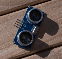
| + | {{Cell2|ultrasoundranger.jpg|Ultrasonic rangefinder board}} | ||
| + | |- | ||
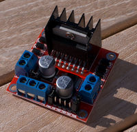
| + | {{Cell|hbridge.jpg|Dual H-bridge module}} | ||
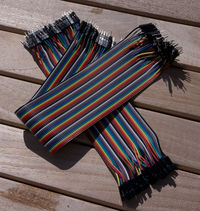
| + | {{Cell|cablesoflurve.jpg|Cables of lurve}} | ||
| + | |||
|} | |} | ||
=== Arduinos === | === Arduinos === | ||
| − | ;6x Arduino Nano v3 | + | ;{{Done|6x Arduino Nano v3}} |
: Breadboard compatible Arduinos with ATMega328 processors. Note that the 3.3v rail is driven from the FTDI chip (the part that interfaces with USB) so is only available when powered through the USB cable (in other cases use a 3.3v regulator). If supplying external power remember to use the VIn pin and not the 5v one, even if you think you have a regulated power supply. | : Breadboard compatible Arduinos with ATMega328 processors. Note that the 3.3v rail is driven from the FTDI chip (the part that interfaces with USB) so is only available when powered through the USB cable (in other cases use a 3.3v regulator). If supplying external power remember to use the VIn pin and not the 5v one, even if you think you have a regulated power supply. | ||
| Line 46: | Line 55: | ||
: These modules break out the three usable pins on the DHT11 sensors | : These modules break out the three usable pins on the DHT11 sensors | ||
| − | ;MPU6050 based 6 axis motion sensor board | + | ;{{Done|MPU6050 based 6 axis motion sensor board}} |
: I2C based motion processor, contains a 3 axis gyroscope in conjunction with a 3 axis linear accelerometer and an embedded DSP | : I2C based motion processor, contains a 3 axis gyroscope in conjunction with a 3 axis linear accelerometer and an embedded DSP | ||
| Line 52: | Line 61: | ||
: Not tested yet, but believed to be a [http://learn.adafruit.com/bmp085/using-the-bmp085-api-v2 BMP085], which if so is capable of resolving pressure differences corresponding to about 20cm of altitude, very nifty! | : Not tested yet, but believed to be a [http://learn.adafruit.com/bmp085/using-the-bmp085-api-v2 BMP085], which if so is capable of resolving pressure differences corresponding to about 20cm of altitude, very nifty! | ||
| − | ;Ultrasonic rangefinders | + | ;{{Done|Ultrasonic rangefinders}} |
: Modules with an ultrasonic emitter / receiver pair and the logic to calculate distance to a reflecting object based on timing. | : Modules with an ultrasonic emitter / receiver pair and the logic to calculate distance to a reflecting object based on timing. | ||
=== Motors and other Output Devices === | === Motors and other Output Devices === | ||
| − | ;12x Dual H-bridge modules, used to drive regular and stepper motors | + | ;{{Done|12x Dual H-bridge modules, used to drive regular and stepper motors}} |
: H-Bridge modules, used to interface to high power devices including motors and drive them from the logic level signals on the Arduino. | : H-Bridge modules, used to interface to high power devices including motors and drive them from the logic level signals on the Arduino. | ||
| Line 63: | Line 72: | ||
: A tough servo with the servo bits removed, now just acts as a high quality electric motor with a gearbox. Drive at 5-6v and use conventional PWM / H-Bridge to alter its speed and direction. | : A tough servo with the servo bits removed, now just acts as a high quality electric motor with a gearbox. Drive at 5-6v and use conventional PWM / H-Bridge to alter its speed and direction. | ||
| − | ;10x 9g servo motors | + | ;{{Done|10x 9g servo motors}} |
| − | : | + | : Basic servo motors. Use the Servo or modified Servo2 library (the latter for when you need to drive more than a couple of servos at a time from the Arduino) |
;{{Done|4x 5V stepper motors with driver boards}} | ;{{Done|4x 5V stepper motors with driver boards}} | ||
| Line 72: | Line 81: | ||
;{{Done|10x NRF24L01 Radio Modules}} | ;{{Done|10x NRF24L01 Radio Modules}} | ||
| − | : Short range radio modules, use the mIRF library. | + | : Short range radio modules, use the mIRF library. (edit - we've lost one, there are now nine of them....) |
| − | ;2x Arduino nano ethernet shields | + | ;{{Done|2x Arduino nano ethernet shields}} |
: Stackable modules providing an ethernet jack | : Stackable modules providing an ethernet jack | ||
| + | |||
| + | Useful library here: https://github.com/ntruchsess/arduino_uip | ||
| + | |||
| + | To use: | ||
| + | |||
| + | cd [path to Arduino distribution]\libraries | ||
| + | git clone https://github.com/ntruchsess/arduino_uip UIPEthernet | ||
| + | |||
| + | There are examples included, which you'll want to tinker with to suit your network. | ||
=== LEDs and displays === | === LEDs and displays === | ||
| Line 84: | Line 102: | ||
;{{Done|4x LED Dot matrix modules with drivers}} | ;{{Done|4x LED Dot matrix modules with drivers}} | ||
: Dot matrix displays, single colour with drivers | : Dot matrix displays, single colour with drivers | ||
| + | |||
| + | <span style='font-family: monospace; display: block; margin-left: 10px; margin-right: 10px; margin-top: 10px; margin-bottom: 10px; padding: 6px; border: 1px solid #aaa; font-size: 12px; line-height: 15px;background-color: #f9f9f9;'><span style='color: #7E7E7E;'>/* MAX7219 Example </span><br> | ||
| + | <span style='color: #7E7E7E;'> * Tom Oinn, 16th September 2013</span><br> | ||
| + | <span style='color: #7E7E7E;'> * Drive our dot matrix and 7+1 segment displays using the LedControl </span><br> | ||
| + | <span style='color: #7E7E7E;'> * library, download from http://playground.arduino.cc/Main/LedControl</span><br> | ||
| + | <span style='color: #7E7E7E;'> */</span><br> | ||
| + | #include <<span style='color: #CC6600;'>LedControl</span>.h><br> | ||
| + | <br> | ||
| + | <span style='color: #7E7E7E;'>/* Digital pin connected to the 'DIN' on the module */</span><br> | ||
| + | <span style='color: #CC6600;'>int</span> DATA = 5;<br> | ||
| + | <span style='color: #7E7E7E;'>/* Digital pin connected to the 'CS' on the module */</span><br> | ||
| + | <span style='color: #CC6600;'>int</span> CS = 6;<br> | ||
| + | <span style='color: #7E7E7E;'>/* Digital pin connected to the 'CLK' on the module */</span><br> | ||
| + | <span style='color: #CC6600;'>int</span> CLOCK = 7;<br> | ||
| + | <br> | ||
| + | <span style='color: #7E7E7E;'>/* </span><br> | ||
| + | <span style='color: #7E7E7E;'> * Number of displays connected, more displays can be chained</span><br> | ||
| + | <span style='color: #7E7E7E;'> * together by connecting the (hopefully) obvious pins. Displays</span><br> | ||
| + | <span style='color: #7E7E7E;'> * are numbered with display 1 being at the end of the chain if</span><br> | ||
| + | <span style='color: #7E7E7E;'> * you have more than one.</span><br> | ||
| + | <span style='color: #7E7E7E;'> */</span><br> | ||
| + | <span style='color: #CC6600;'>int</span> DISPLAYS = 3;<br> | ||
| + | <br> | ||
| + | <span style='color: #7E7E7E;'>/* </span><br> | ||
| + | <span style='color: #7E7E7E;'> * Create a new LedControl object, passing in the data, </span><br> | ||
| + | <span style='color: #7E7E7E;'> * clock, chip select and number of displays </span><br> | ||
| + | <span style='color: #7E7E7E;'> */</span><br> | ||
| + | <span style='color: #CC6600;'>LedControl</span> lc = <span style='color: #CC6600;'>LedControl</span>(DATA, CLOCK, CS, DISPLAYS);<br> | ||
| + | <br> | ||
| + | <span style='color: #7E7E7E;'>/* Initialise the displays */</span><br> | ||
| + | <span style='color: #CC6600;'>void</span> <span style='color: #CC6600;'><b>setup</b></span>() {<br> | ||
| + | <span style='color: #CC6600;'>for</span> (<span style='color: #CC6600;'>int</span> n = 0; n < DISPLAYS; n++) {<br> | ||
| + | lc.<span style='color: #CC6600;'>shutdown</span>(n,<span style='color: #CC6600;'>false</span>);<br> | ||
| + | lc.<span style='color: #CC6600;'>setIntensity</span>(n,8);<br> | ||
| + | lc.<span style='color: #CC6600;'>clearDisplay</span>(n);<br> | ||
| + | }<br> | ||
| + | }<br> | ||
| + | <br> | ||
| + | <span style='color: #7E7E7E;'>/* Used to allow the sin wave to animate */</span><br> | ||
| + | <span style='color: #CC6600;'>float</span> offset = 0.0;<br> | ||
| + | <br> | ||
| + | <span style='color: #CC6600;'>void</span> <span style='color: #CC6600;'><b>loop</b></span>() {<br> | ||
| + | <span style='color: #7E7E7E;'>/* Iterate over the total number of rows, i.e. DISPLAYS * 8 */</span><br> | ||
| + | <span style='color: #CC6600;'>for</span> (<span style='color: #CC6600;'>int</span> i = 0 ; i < DISPLAYS <<3; i++) {<br> | ||
| + | <span style='color: #7E7E7E;'>/* For each row work out where we want the dot for a sin wave */</span><br> | ||
| + | <span style='color: #CC6600;'>int</span> shift = (<span style='color: #CC6600;'>int</span>)((<span style='color: #CC6600;'>sin</span>(offset + ((<span style='color: #CC6600;'>float</span>)(i)*0.6))+1.0)*4.0);<br> | ||
| + | <span style='color: #7E7E7E;'>/* </span><br> | ||
| + | <span style='color: #7E7E7E;'> * Set the row to be that value, we'd use columns but our</span><br> | ||
| + | <span style='color: #7E7E7E;'> * are the wrong shape on the boards to do that. Columns would</span><br> | ||
| + | <span style='color: #7E7E7E;'> * be more efficient and require fewer shift operations internally</span><br> | ||
| + | <span style='color: #7E7E7E;'> */</span><br> | ||
| + | lc.setRow(i>>3, i & 7, 1<<shift); <br> | ||
| + | }<br> | ||
| + | <span style='color: #7E7E7E;'>/* Increment the offset, add a delay and go around again */</span><br> | ||
| + | offset += <span style='color: #006699;'>PI</span> / 16;<br> | ||
| + | <span style='color: #CC6600;'>delay</span>(50);<br> | ||
| + | }<br> | ||
| + | </span> | ||
;{{Done|2x Eight digit seven segment displays with drivers}} | ;{{Done|2x Eight digit seven segment displays with drivers}} | ||
: Standard 'calculator style' seven segment displays in a module of eight of them with associated driver circuitry. | : Standard 'calculator style' seven segment displays in a module of eight of them with associated driver circuitry. | ||
| + | : [https://www.sparkfun.com/datasheets/Components/General/COM-09622-MAX7219-MAX7221.pdf MAX7219 Datasheet] | ||
| − | ;4x LCD 20x4 character displays | + | ;{{Done|4x LCD 20x4 character displays}} |
: LCD character displays, serial protocol (probably!) to drive them. | : LCD character displays, serial protocol (probably!) to drive them. | ||
| Line 99: | Line 176: | ||
: Analogue joysticks with an embedded press button | : Analogue joysticks with an embedded press button | ||
| − | ;Male to male and male to female jumper leads | + | ;{{Done|Male to male and male to female jumper leads}} |
| − | : A load of long jump leads with pins and sockets (depending on type) to make it easier to interface to modules such as the NRF24L which have otherwise awkward pin layouts and can't be directly connected to a breadboard. | + | : A load of long jump leads with pins and sockets (depending on type) to make it easier to interface to modules such as the NRF24L which have otherwise awkward pin layouts and can't be directly connected to a breadboard. Update - these are now here, and are so full of lurve that they're unsafe to use unless you are singing 'The Power of Love' by Huey Lewis and the News while doing so. This will be enforced. |
== Requests == | == Requests == | ||
Put your requests for parts here... | Put your requests for parts here... | ||
| + | |||
| + | At the moment I think we could do with some regular DC motors, some switches, potentiometers, piezo speakers and battery packs (ideally with a few regulator boards capable of providing clean 3.3v, 5v and possibly 12v feeds from the same). We can make the boards, potentially. Even better for power would be a few LiPo packs, again with regulators and suitable chargers. | ||
Latest revision as of 20:18, 14 March 2018
(see also The Arduino and Cake main page)
Contents
Big Box of Breakout Boards and Bits
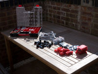
We have a box of bits containing Arduinos for use in the space along with an assortment of sensors, motors, lights and other things you might need to make up a project. It lives in... (to be confirmed, currently it lives in my kitchen, obviously that won't be its final location!)
This page exists to catalogue the contents of the box along with any notes on how to use each modules, including links to Arduino libraries, datasheets, photos showing pinouts and suchlike. Basically if you've figured out how to use a module through extensive googling and experimentation here is where you can share that knowledge with everyone else. Use your signatures to claim credit!
Policies
This is not primarily intended to be used as stock for people's projects, rather it's there to provide a lending library of parts for use at events such as the Arduino and Cake sessions and Family Makers. That said, none of the parts are particularly expensive and we try to have a reasonable number of them so if you really need something for a project right now, aren't going to be taking the last one of something and are prepared to provide a replacement in non ludicrous time that's probably fine. If unsure ask on the mailing list! Most things here have been bought from sellers from the far East on eBay, so while they're cheap the lead times are often quite lengthy.
There's a section at the end of this page for requests - if there's something you'd like to have access to and which is of general use (i.e. not for just one project you have in mind) add some details and we'll see whether we can source it at an appropriate price. If something goes wrong and the magic white smoke escapes from something please make a note in the section for the component or module concerned, that way we know it's broken and can either fix or replace it (and tell everyone how to avoid the same thing happening again)
What's in the Box?
Contents of the box, both current and planned. Things that have arrived and are ready for use are marked in this colour. We need photos and documentation for everything on this list!
| Spotter's Guide | |||
|---|---|---|---|
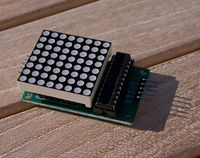
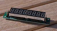
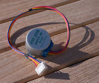
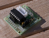
| Max7219 based dot matrix display | Max7219 based seven segment LED display | 5v stepper motor | Driver board for 5v stepper motor |
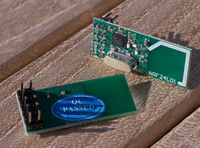
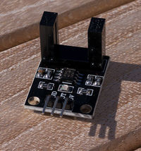
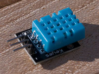
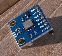
| NRF24L01 radio modules | IR beam break detector | DHT11 temperature / humidity sensor | Barometric pressure sensor |
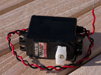
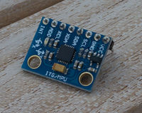
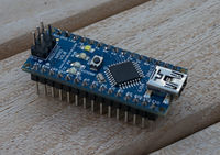
| Geared 6v motor (ex servo) | Assorted pink, green, orange and blue LEDs | MPU6050 six axis motion sensor | Arduino nano v3 |
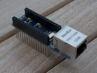
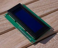
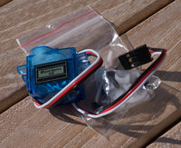
| Arduino nano ethernet shield | Blue LCD display | 9g servo and accessories | Ultrasonic rangefinder board |
| Dual H-bridge module | Cables of lurve | ||
Arduinos
- 6x Arduino Nano v3
- Breadboard compatible Arduinos with ATMega328 processors. Note that the 3.3v rail is driven from the FTDI chip (the part that interfaces with USB) so is only available when powered through the USB cable (in other cases use a 3.3v regulator). If supplying external power remember to use the VIn pin and not the 5v one, even if you think you have a regulated power supply.
Sensors and Input Devices
- 3x DHT11 temperature and humidity Sensors
- These modules break out the three usable pins on the DHT11 sensors
- MPU6050 based 6 axis motion sensor board
- I2C based motion processor, contains a 3 axis gyroscope in conjunction with a 3 axis linear accelerometer and an embedded DSP
- 1x Barometric pressure sensor board
- Not tested yet, but believed to be a BMP085, which if so is capable of resolving pressure differences corresponding to about 20cm of altitude, very nifty!
- Ultrasonic rangefinders
- Modules with an ultrasonic emitter / receiver pair and the logic to calculate distance to a reflecting object based on timing.
Motors and other Output Devices
- 12x Dual H-bridge modules, used to drive regular and stepper motors
- H-Bridge modules, used to interface to high power devices including motors and drive them from the logic level signals on the Arduino.
- 1x hacked HiTec HS-625MG
- A tough servo with the servo bits removed, now just acts as a high quality electric motor with a gearbox. Drive at 5-6v and use conventional PWM / H-Bridge to alter its speed and direction.
- 10x 9g servo motors
- Basic servo motors. Use the Servo or modified Servo2 library (the latter for when you need to drive more than a couple of servos at a time from the Arduino)
- 4x 5V stepper motors with driver boards
- Document how to make them work here (Martin?) - there's more info on these exact boards along with example code here, yet to be tried but they look identical!
Communications
- 10x NRF24L01 Radio Modules
- Short range radio modules, use the mIRF library. (edit - we've lost one, there are now nine of them....)
- 2x Arduino nano ethernet shields
- Stackable modules providing an ethernet jack
Useful library here: https://github.com/ntruchsess/arduino_uip
To use:
   cd [path to Arduino distribution]\libraries
   git clone https://github.com/ntruchsess/arduino_uip UIPEthernet
There are examples included, which you'll want to tinker with to suit your network.
LEDs and displays
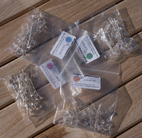
- High brightness LEDs
- 20 each of four different colours (pink, green, blue and orange) 5mm LEDs, remember to use current limiting resistors or a constant current source when driving them!
- 4x LED Dot matrix modules with drivers
- Dot matrix displays, single colour with drivers
/* MAX7219 Example
* Tom Oinn, 16th September 2013
* Drive our dot matrix and 7+1 segment displays using the LedControl
* library, download from http://playground.arduino.cc/Main/LedControl
*/
#include <LedControl.h>
/* Digital pin connected to the 'DIN' on the module */
int DATA = 5;
/* Digital pin connected to the 'CS' on the module */
int CS = 6;
/* Digital pin connected to the 'CLK' on the module */
int CLOCK = 7;
/*
* Number of displays connected, more displays can be chained
* together by connecting the (hopefully) obvious pins. Displays
* are numbered with display 1 being at the end of the chain if
* you have more than one.
*/
int DISPLAYS = 3;
/*
* Create a new LedControl object, passing in the data,
* clock, chip select and number of displays
*/
LedControl lc = LedControl(DATA, CLOCK, CS, DISPLAYS);
/* Initialise the displays */
void setup() {
for (int n = 0; n < DISPLAYS; n++) {
lc.shutdown(n,false);
lc.setIntensity(n,8);
lc.clearDisplay(n);
}
}
/* Used to allow the sin wave to animate */
float offset = 0.0;
void loop() {
/* Iterate over the total number of rows, i.e. DISPLAYS * 8 */
for (int i = 0 ; i < DISPLAYS <<3; i++) {
/* For each row work out where we want the dot for a sin wave */
int shift = (int)((sin(offset + ((float)(i)*0.6))+1.0)*4.0);
/*
* Set the row to be that value, we'd use columns but our
* are the wrong shape on the boards to do that. Columns would
* be more efficient and require fewer shift operations internally
*/
lc.setRow(i>>3, i & 7, 1<<shift);
}
/* Increment the offset, add a delay and go around again */
offset += PI / 16;
delay(50);
}
- 2x Eight digit seven segment displays with drivers
- Standard 'calculator style' seven segment displays in a module of eight of them with associated driver circuitry.
- MAX7219 Datasheet
- 4x LCD 20x4 character displays
- LCD character displays, serial protocol (probably!) to drive them.
Everything else
- 2x IR correlation modules
- IR beam break sensors with amplifiers to provide a clean signal. Not tested yet!
- 10x Playstation style joysticks
- Analogue joysticks with an embedded press button
- Male to male and male to female jumper leads
- A load of long jump leads with pins and sockets (depending on type) to make it easier to interface to modules such as the NRF24L which have otherwise awkward pin layouts and can't be directly connected to a breadboard. Update - these are now here, and are so full of lurve that they're unsafe to use unless you are singing 'The Power of Love' by Huey Lewis and the News while doing so. This will be enforced.
Requests
Put your requests for parts here...
At the moment I think we could do with some regular DC motors, some switches, potentiometers, piezo speakers and battery packs (ideally with a few regulator boards capable of providing clean 3.3v, 5v and possibly 12v feeds from the same). We can make the boards, potentially. Even better for power would be a few LiPo packs, again with regulators and suitable chargers.
